Table of Contents
Overview
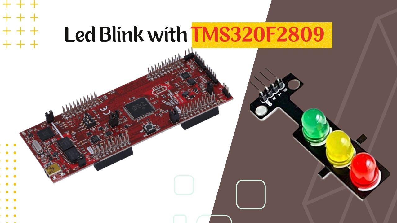
Texas Instruments TMS320F28069 microcontroller is a potent component that may be applied to a variety of tasks. We’ll walk you through setting up and programming this microcontroller to blink LEDs in this tutorial. We’ll go over pin connections, explain the coding, and give you a complete example to follow.
Prerequisites
- Before we begin, make sure you have the following:
- TMS320F28069 LaunchPad or a compatible development board.
- Code Composer Studio (CCS) or another suitable Integrated Development Environment (IDE) installed.
- Basic knowledge of C programming.
GPIO Configuration Steps
When dealing with embedded systems, configuring GPIO (General Purpose Input/Output) pins on a microcontroller is an essential task. GPIO pins let you control or read digital signals from a variety of external devices. The general steps to configure GPIO pins are as follows:
Select the GPIO Pins:
Determine which GPIO pins you want to configure for your application. Refer to the microcontroller’s datasheet or reference manual to identify the available GPIO pins and their locations on the chip.
Set Pin Direction:
- Decide whether each selected pin will be an input or an output.
- To configure a pin as an output, set the corresponding bit in the GPIO direction register (e.g., GPIODIR).
- To configure a pin as an input, clear the corresponding bit in the direction register.
Enable/Disable Pull-up or Pull-down Resistors:
- Decide whether you need to enable internal pull-up or pull-down resistors for input pins. These resistors help to stabilize the voltage levels on input pins.
- To enable a pull-up resistor, set the corresponding bit in the GPIO pull-up register.
- To enable a pull-down resistor, set the corresponding bit in the GPIO pull-down register.
Select Alternate Functions (if necessary):
- Some GPIO pins on microcontrollers have alternate functions, such as UART, SPI, I2C, PWM, etc. If you intend to use a pin for one of these functions, you may need to configure it as an alternate function pin.
- Configure the pin multiplexer registers to select the appropriate alternate function for the pin.
Configure Input Qualification (if necessary):
- Input qualification settings help filter noisy input signals and provide more stable inputs.
- Configure input qualification registers (e.g., GPIOAQSEL) to set up the input qualification type and level for the pins.
GpioCtrlRegs structure
The GpioCtrlRegs structure is a part of the TMS320F28069 microcontroller’s peripheral registers, specifically related to GPIO (General Purpose Input/Output) control. This structure provides control and configuration for the GPIO pins on the microcontroller. Let’s take a detailed look at some of the important members of this structure:
GPAMUX1 to GPBMUX2 (32-bit registers):
These registers configure the multiplexer settings for GPIO pins in two 32-pin groups (Group A and Group B). They control whether a pin should function as a GPIO pin or be used for an alternate peripheral function.
GPAQSEL1 to GPBQSEL2 (32-bit registers):
These registers configure the input qualification settings for GPIO pins in two 32-pin groups (Group A and Group B). Input qualification helps filter noisy input signals and provides more stable GPIO inputs.
GPADIR and GPBDIR (32-bit registers):
These registers determine the direction of the GPIO pins in two 32-pin groups (Group A and Group B). Setting a bit to 1 configures the corresponding pin as an output while setting it to 0 configures the pin as an input.
GPAPUD and GPBPUD (32-bit registers):
These registers control the pull-up and pull-down resistors for GPIO pins in two 32-pin groups (Group A and Group B). Setting a bit to 1 enables the internal pull-up resistor while setting it to 0 disables it. These resistors are used to stabilize the voltage levels on input pins.
GPAQSEL1 to GPAQSEL2 (32-bit registers):
These registers configure the asynchronous qualification settings for GPIO pins in two 32-pin groups (Group A and Group B). The asynchronous qualification allows the GPIO pin to respond immediately to changes in the input signal.
GPBCTRL (32-bit register):
This register controls the input filter settings for Group B GPIO pins. It allows you to configure the filter input response time.
GPBGMUX1 to GPBGMUX2 (32-bit registers):
These registers configure the GPIO pin group B multiplexer settings for specialized peripheral signals. They are used for selecting alternate peripheral functions for GPIO pins in Group B.
GPBQSEL1 to GPBQSEL2 (32-bit registers):
These registers configure the input qualification settings for GPIO pins in Group B. Similar to GPAQSEL1 to GPAQSEL2, they provide input qualification settings but for pins in Group B.
Setting up the Hardware
In this example, we’ll use two LEDs linked to GPIO34 and GPIO39 pins to demonstrate how to connect the LEDs. The first LED’s anode (longer lead) should be connected to GPIO34, while the second LED’s anode should be connected to GPIO39. Connect the ground (GND) pin on the circuit board to the cathode (shorter lead) of both LEDs.
Power Supply:
Make that your board is powered, either by a USB source or a separate power source.
Writing the Code
Let’s start by analyzing the code you gave and explaining each section.
#include "DSP28x_Project.h"

#define Led1_ON      GpioDataRegs.GPBCLEAR.bit.GPIO34
#define Led1_Off     GpioDataRegs.GPBSET.bit.GPIO34
#define Led1_Toggle  GpioDataRegs.GPBTOGGLE.bit.GPIO34

#define Led2_ON      GpioDataRegs.GPBCLEAR.bit.GPIO39
#define Led2_Off     GpioDataRegs.GPBSET.bit.GPIO39
#define Led2_Toggle  GpioDataRegs.GPBTOGGLE.bit.GPIO39
You create macros to control the LEDs in this part. These macros make it simple to control the associated GPIO pins to turn the LEDs on, off, or toggle their state.
void delay(double d_i);

void main(void)
{
    InitSysCtrl();
    InitGpio();
    InitSysCtrl();
    InitGpio();
The GPIO settings and system control are initialized here. While InitGpio() initializes the GPIO pins, InitSysCtrl() configures the system control. These functions shouldn’t typically be called twice in a row; you can safely eliminate one of each.
    EALLOW;
    GpioCtrlRegs.GPBMUX1.bit.GPIO34 = 0; // GPIO34 - General purpose I/O
    GpioCtrlRegs.GPBDIR.bit.GPIO34 = 1; // 1 = Configures the GPIO pin as an output
    GpioCtrlRegs.GPBPUD.bit.GPIO34 = 1;

    GpioCtrlRegs.GPBMUX1.bit.GPIO39 = 0; // GPIO39 - General purpose I/O
    GpioCtrlRegs.GPBDIR.bit.GPIO39 = 1; // 1 = Configures the GPIO pin as an output
    GpioCtrlRegs.GPBPUD.bit.GPIO39 = 1;
    EDIS;
Final code
#include "DSP28x_Project.h"

#define Led1_ON      GpioDataRegs.GPBCLEAR.bit.GPIO34
#define Led1_Off     GpioDataRegs.GPBSET.bit.GPIO34
#define Led1_Toggle  GpioDataRegs.GPBTOGGLE.bit.GPIO34


#define Led2_ON      GpioDataRegs.GPBCLEAR.bit.GPIO39
#define Led2_Off     GpioDataRegs.GPBSET.bit.GPIO39
#define Led2_Toggle  GpioDataRegs.GPBTOGGLE.bit.GPIO39

void delay(double d_i);

void main(void)
{

    InitSysCtrl();
    InitGpio();
    InitSysCtrl();
    InitGpio();

    EALLOW;
    GpioCtrlRegs.GPBMUX1.bit.GPIO34     = 0;        // GPIO20 - General purpose I/O
    GpioCtrlRegs.GPBDIR.bit.GPIO34      = 1;        // 0 = Configures the GPIO pin as an input. 1 = Configures the GPIO pin as an output
    GpioCtrlRegs.GPBPUD.bit.GPIO34      = 1;


    GpioCtrlRegs.GPBMUX1.bit.GPIO39     = 0;        // GPIO21 - General purpose I/O
    GpioCtrlRegs.GPBDIR.bit.GPIO39      = 1;        // 0 = Configures the GPIO pin as an input. 1 = Configures the GPIO pin as an output
    GpioCtrlRegs.GPBPUD.bit.GPIO39      = 1;
    EDIS;

    while(1)
    {
        Led1_Toggle = 1;
        delay(400000);
        Led2_Toggle  = 1;
        delay(400000);
    }

}


void delay(double d_i) {
    double i = 0;
    while (i++ < d_i);
}