Table of Contents
Overview
The Analog-to-Digital Converter (ADC) module of the TMS320F28069 microcontroller, a flexible embedded system powerhouse, is an essential part. The ability to convert analog signals into digital data is made possible by this module, which is a critical capability for a variety of applications, from sensor interface to data collecting. To ensure accurate voltage readings, we will go into great detail in this extensive manual about how to set up and use the ADC with interrupts on the TMS320F28069.
Introduction to ADC on TMS320F28069
A 12-bit successive approximation register (SAR) type ADC is the one found in the TMS320F28069. It can be used for a variety of applications, including sensor interface and data gathering because it offers high-resolution analog-to-digital conversion.
Key Parameters
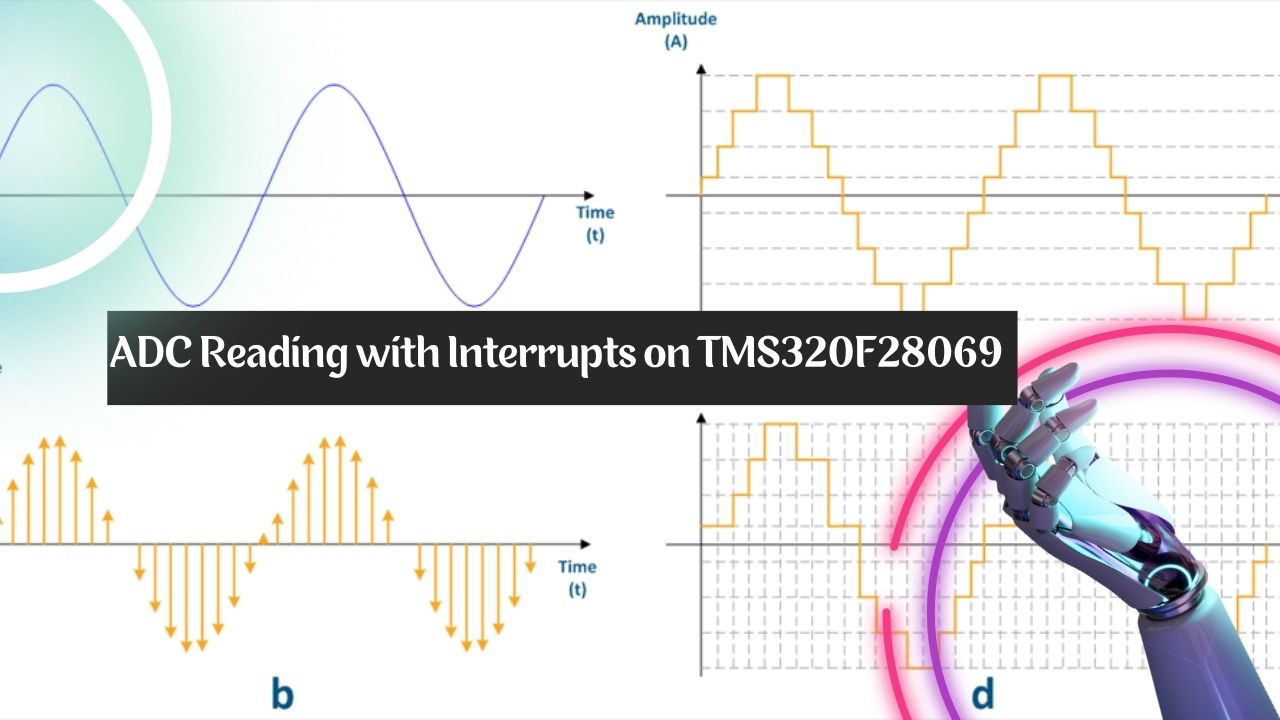
- Resolution: The ADC provides a 12-bit resolution, which means it can represent analog signals in 4096 discrete steps (2^12).
- Sampling Rate: The speed at which the ADC can sample and convert an analog signal is determined by the system clock and the ADC configuration.

Code Overview
Let’s take a quick look at the provided code before going into the specifics of reading ADC values with interrupts. The ADC is configured to read two analog channels, ADCINA0 and ADCINA1, and the ADC conversions are handled by an interrupt in this code.
void main(void)
{
    // Initialization code...
    InitAdc();
    InitAdcAio();
    ADC_Inint();

    // Interrupt setup...
    AdcRegs.ADCSOCFRC1.all = 0x03;
    while(1)
    {
        AdcRegs.ADCSOCFRC1.all = 0x03;
    }
}
Initialization Functions
InitADC()
The ADC module is initialized via this function. It configures the ADC’s reference voltage and clock source. You should make sure that this function is correctly configured for the needs of your particular application given that it is called as InitAdc() in your code.
InitAdcAIO()
The analog input pins (in this case, ADCINA0 and ADCINA1) are configured using this function. It turns on the ADC channels you intend to utilize and correctly configures pin muxing.
ADC_Inint()
The ADC interrupt is set up using this function. It sets up the ADC to send out an interrupt after the conversion is finished.
ADC Configuration
Interrupt Configuration
In the provided code, the interrupt is configured to trigger when the ADC conversion is complete (EOC1 signal). Here’s how it’s done:
AdcRegs.ADCCTL1.bit.INTPULSEPOS = 1; // ADCINT1 triggers after AdcResults latch
AdcRegs.INTSEL1N2.bit.INT1E = 1; // Enable ADCINT1
AdcRegs.INTSEL1N2.bit.INT1CONT = 0; // Disable continuous mode
AdcRegs.INTSEL1N2.bit.INT1SEL = 1; // Setup EOC1 to trigger ADCINT1
Here’s what each setting does:
- INTPULSEPOS: Configures when the interrupt pulse is generated relative to the result latch. Setting it to 1 ensures the interrupt triggers after the ADC result latch.
- INT1E: Enables ADCINT1.
- INT1CONT: Disables continuous mode for the ADC interrupt.
- INT1SEL: Sets up End Of Conversion (EOC) for channel 15 to trigger ADCINT1.
ADC Channels and Triggers
The code has two ADC channels configured, ADCINA0 and ADCINA1. By setting TRIGSEL to 0, they are configured to initiate conversions manually (software trigger):


AdcRegs.ADCSOC0CTL.bit.CHSEL = 0; // SOC0 channel select to ADCINA0
AdcRegs.ADCSOC1CTL.bit.CHSEL = 1; // SOC1 channel select to ADCINA1
AdcRegs.ADCSOC0CTL.bit.TRIGSEL = 0; // SOC0 start trigger on SW
AdcRegs.ADCSOC1CTL.bit.TRIGSEL = 0; // SOC1 start trigger on SW
ADC Sampling Window
The ACQPS (Acquisition Prescale) value is used to determine the length of the sample window. The sampling window will be 7 ADC clock cycles (6 ACQPS plus 1) because it is set to 6 in your code.


AdcRegs.ADCSOC0CTL.bit.ACQPS = 6; // SOC0 S/H Window set to 7 ADC Clock Cycles
AdcRegs.ADCSOC1CTL.bit.ACQPS = 6; // SOC1 S/H Window set to 7 ADC Clock Cycles
ADC Interrupt Service Routine
The real ADC results are recorded and processed in the ADC interrupt service procedure (adc_isr). The outcomes of ADCINA0 and ADCINA1 are saved in Voltage1 and Voltage2, respectively, in your code.

ADC Interrupt Flag Clear Register (ADCINTFLGCLR)


Voltage1 = AdcResult.ADCRESULT0; // Store result for ADCINA0 in Voltage1
Voltage2 = AdcResult.ADCRESULT1; // Store result for ADCINA1 in Voltage2
AdcRegs.ADCINTFLGCLR.bit.ADCINT1 = 1; // Clear ADCINT1 flag
PieCtrlRegs.PIEACK.all = PIEACK_GROUP1; // Acknowledge interrupt
Voltage Conversion
You can use the following formula to translate ADC values into voltage:
Reference Voltage = 3.294;

Final Code
#include "DSP28x_Project.h"


#define NUM_SAMPLES 16   // Number of samples to average
#define BUFFER_MASK (NUM_SAMPLES - 1)


void InitADC(void);
void InitAdcAIO(void);
void ADC_Inint(void);
void AdcSocConfig(void);


__interrupt void  adc_isr (void);

Uint16 Voltage1;
Uint16 Voltage2;


void main(void)
{
    InitSysCtrl();
    InitPieCtrl();
    InitPieVectTable();
    InitGpio();


    InitAdc();
    InitAdcAio();
    ADC_Inint();

    EALLOW;
    PieVectTable.ADCINT1 = &adc_isr;
    EDIS;

    PieCtrlRegs.PIEIER1.bit.INTx1 = 1;
    IER |= M_INT1;

    EINT;
    ERTM;


    AdcRegs.ADCSOCFRC1.all = 0x03;
    while(1)
    {
        AdcRegs.ADCSOCFRC1.all = 0x03;
    }

}


void ADC_Inint(void)
{
    EALLOW;
      AdcRegs.ADCCTL1.bit.INTPULSEPOS   = 1;    //ADCINT1 trips after AdcResults latch
      AdcRegs.INTSEL1N2.bit.INT1E       = 1;    //Enabled ADCINT1
      AdcRegs.INTSEL1N2.bit.INT1CONT    = 0;    //Disable ADCINT1 Continuous mode
      AdcRegs.INTSEL1N2.bit.INT1SEL     = 1;   //setup EOC15 to trigger ADCINT1 to fire

      AdcRegs.ADCSOC0CTL.bit.CHSEL      = 0;    //set SOC0 channel select to ADCINA0
      AdcRegs.ADCSOC1CTL.bit.CHSEL      = 1;    //set SOC1 channel select to ADCINA1

      AdcRegs.ADCSOC0CTL.bit.TRIGSEL    = 0;    //set SOC0 start trigger on SW
      AdcRegs.ADCSOC1CTL.bit.TRIGSEL    = 0;    //set SOC1 start trigger on SW

      AdcRegs.ADCINTSOCSEL1.bit.SOC0    = 1;     //ADCINT1 will trigger SOC0
      AdcRegs.ADCINTSOCSEL1.bit.SOC1    = 1;     //ADCINT1 will trigger SOC1


      AdcRegs.ADCSOC0CTL.bit.ACQPS      = 6;   //set SOC0 S/H Window to 7 ADC Clock Cycles, (6 ACQPS plus 1)
      AdcRegs.ADCSOC1CTL.bit.ACQPS      = 6;   //set SOC0 S/H Window to 7 ADC Clock Cycles, (6 ACQPS plus 1)

      EDIS;

}


__interrupt void  adc_isr (void)
{


    Voltage1 = AdcResult.ADCRESULT0;
    Voltage2 = AdcResult.ADCRESULT1;
    AdcRegs.ADCINTFLGCLR.bit.ADCINT1 = 1;               //Clear ADCINT1 flag reinitialize for next SOC
    PieCtrlRegs.PIEACK.all = PIEACK_GROUP1;             // Acknowledge interrupt to PIE


}