
Table of Contents
Overview
This is a series of robots that uses three wheels to drive over almost any terrain. Works on any interior and exterior surface. This robot uses Android technology. This can be moved back and forth using 60RPM geared motors. Also, this robot can make sharp turns to the left and right. This project uses ARDUINO as its controller.
Here the Bluetooth module is used. Bluetooth is a wireless technology standard for exchanging data over short distances (using short-wavelength radio waves in the ISM band 2.4 to 2.485 GHz) from fixed and mobile devices, building personal area networks (PAN). The MCU The purpose of the fire sensor is to detect the fire and this fire sensor bypasses a pulse to the microcontroller each time the fire has been detected. Then the MCU activates the water spray with the help of the relay controller circuit to put out the fire.
This project uses a regulated 5V 500mA power supply. The 7805 and 7812 three-terminal voltage regulators are used to regulate voltage. The bridge type full wave rectifier is used to rectify the secondary AC output of the 230 / 12v step-down transformer.
Block Diagram:

Required Hardware Components
hardware
- ATMEGA328P Microcontroller.
- lm35
- l293d
- bluetooth hc-05
- Relay
Software:
- Arduino compiler
- Proteus designing software
- Embedded c programming
- Flash magic.
Arduino uno
This is the new Arduino Uno R3 made in Italy with a box. In addition to all the features of the previous board, the Uno now uses an ATmega16U2 instead of the 8U2 found in the Uno (or the FTDI found in previous generations). This allows for faster transfer speeds and more memory. No drivers are needed for Linux or Mac (the inf file is needed for Windows and is included in the Arduino IDE), and the ability to display the Uno as a keyboard, mouse, joystick, etc. The Uno R3 also adds SDA and SCL pins alongside the AREF. Also, there are two new pins placed near the RESET pin. One is the IOREF which allows the screens to adapt to the voltage supplied from the board.
The other is not connected and is reserved for future purposes. The Uno R3 works with all existing shields but can be retrofitted to new shields that use these additional pins. Arduino is an open-source physical computing platform based on a simple I / O board and development environment that implements the Processing / Wiring language. Arduino can be used to develop independent interactive objects or it can be connected to your computer software (eg Flash, Processing, MaxMSP). The open-source IDE is free to download (currently for Mac OS X, Windows, and Linux). Features: ATmega328 microcontroller Input voltage – 7-12V 14 digital I / O pins (6 PWM outputs) 6 analog inputs 32k Flash memory 16Mhz clock speed
Tech specs


L293D Motor Driver Shield for Arduino
This L293D motor driver protector for Arduino is probably one of the most versatile on the market and features 2 servo and 4 motor connectors for DC or stepper motors. That makes it a great shield for any robotic project.
This Arduino compatible motor driver protector is a full-featured product that can be used to drive 4 DC motors or two 4-wire stepper motors and two 5V servos. It drives the DC motor and stepper. step by step with the L293D, and drive the servo with Arduino pin9 and pin10.
L293D is a 4 channel high voltage, high current, integrated monolithic controller. Basically, this means that by using this chip you can use DC motors and power supplies up to 36 volts, that some fairly large motors and the chip can supply a maximum current of 600 mA per channel, the L293D chip is also what is known as a type of H-Bridge. The H-Bridge is typically an electrical circuit that allows a voltage to be applied across a load in any direction to an output, eg. Eg an engine.
The shield contains two L293D motor controllers and a 74HC595 shift register. The shift register expands the Arduino’s 3 pins to 8 pins to control the direction of the motor drivers. The output allows the L293D to be connected directly to the Arduino’s PWM outputs.
Features of L293D Motor Driver Shield for Arduino:-


Hc-05 Wireless Bluetooth Rf Transceiver Module Serial/Ttl/Rs232
- Wireless Bluetooth RF Transceiver Module HC-05 RS232 Master Slave for Arduino Feature Bluetooth Serial Transceiver Module with backboard. Works with any USB Bluetooth adapters.
- This module includes key interface and state interface compared with Smart Bluetooth Module Baseboard. The Bluetooth Module Baseboard can be compatible with master mode,slave mode and both master-slave mode.
- Works for Bluetooth TTL transceiver module which allows your target device to both send or receive the TTL data. The key interface on the baseboard is the master mode button and can be controlled by high level from external MCU, then this module will search again automatically.
- This module power supply input is 4.5~6V Use the CSR mainstream bluetooth chip, bluetooth V2.0 protocol standards. Module working voltage 3.3 V. Default rate of 9600, the user can be set up. Working current: matching for 30 MA, matching the communication for 8 MA. Dormancy current: no dormancy.
HC-05 Specifications:-
- Profiles: Bluetooth serial port Profile
- Bluetooth protocol: Bluetooth Specification v2.0+EDR
- Frequency: 2.4GHz ISM band
- Modulation: GFSK(Gaussian Frequency Shift Keying)
- Emission power: ≤4dBm, Class 2
- Sensitivity: ≤-84dBm at 0.1% BER
- Speed: Asynchronous: 2.1Mbps(Max) / 160 kbps, Synchronous: 1Mbps/1Mbps
- Security: Authentication and encryption
- Power supply: +3.3VDC 50mA
- Working temperature: -20 ~ +75Centigrade
- Dimension: 26.9mm x 13mm x 2.2 mm
HC-05 Applications:-
- Embedded Projects
- Industrial Applications
- Computer and portable Devices
- GPS receiver

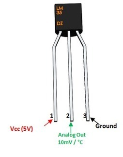
LM35 TO-92-3 Board Mount Temperature Sensors
LM35 is an integrated analog temperature sensor whose electrical output is proportional to degrees centigrade. The LM35 sensor does not require any external calibration or clipping to provide typical accuracies. The LM35’s low output impedance, a linear output, and inherently accurate calibration make interfacing with control or reading circuitry especially easy.
As such, no additional components are required to connect LM35 to ADC as the LM35 output is linear with a scale of 10mv / degree. It can be directly connected to any 10 or 12 bit ADC. But if you are using an 8 bit ADC like ADC0808 or ADC0804, then an amplifier section will be needed if you need to measure 1 ° C change.
LM35 can also be connected directly to Arduino. The temperature output from the LM35 can also be sent to the comparator circuit and can be used for over-temperature indication or, through the use of a simple relay, can be used as a temperature controller.
The LM35 device is rated to operate in a temperature range of −55 ° C to 150 ° C, while the LM35C device is rated for a range of −40 ° C to 110 ° C (−10 ° more accurately). The LM35 series devices are available packaged in sealed TO transistor packages, while the LM35C, LM35CA and LM35D devices are available in plastic TO-92 transistor packages. The LM35D device is available on an 8-lead surface to mount a small contour package and a TO-220 plastic package.
Features:

Pin out

DC Motor – 150RPM – 12Volts geared motors are generally simple DC motors with a gearbox attached to it. This can be used in all-terrain robots and a variety of robotic applications. These motors have a 3 mm threaded drill hole in the middle of the shaft thus making it simple to connect it to the wheels or any other mechanical assembly.
150 RPM 12V DC geared motors widely use for robotics applications. Very easy to use and available in standard size. Also, you don’t have to spend a lot of money to control motors with an Arduino or compatible board. The most popular L298N H-bridge module with onboard voltage regulator motor driver can be used with this motor that has a voltage of between 5 and 35V DC or you can choose the most precise motor diver module from the wide range available in our Motor divers category as per your specific requirements.
Nut and threads on the shaft to easily connect and internally threaded shaft for easily connecting it to the wheel.DC Geared motors with robust metal gearbox for heavy-duty applications, available in the wide RPM range and ideally suited for robotics and industrial applications.Very easy to use and available in standard size. Nut and threads on the shaft to easily connect and internally threaded shaft for easily connecting it to the wheel.
Specifications and Features:-
- RPM: 150.
- Operating Voltage: 12V DC
- Gearbox: Attached Plastic (spur)Gearbox
- Shaft diameter: 6mm with internal hole
- Torque: 2 kg-cm
- No-load current = 60 mA(Max)
- Load current = 300 mA(Max).
* Product Images are shown for illustrative purposes only and may differ from the actual products.
150 RPM – 12V Centre Shaft DC Geared Motor
DC Motor – 150 RPM – 12 volt geared motors are generally simple DC motors with an attached gearbox. This can be used in off-road robots and a variety of robotic applications. These motors have a 3mm threaded hole in the middle of the axle, which makes it easy to connect them to the wheels or any other mechanical assembly.
150 RPM 12V DC geared motors are widely used for robotics applications. Very easy to use and available in standard size. Also, you don’t have to spend a lot of money to control motors with an Arduino or compatible board. The most popular L298N H-bridge module with integrated voltage regulator motor controller can be used with this motor which has a voltage between 5 and 35V DC or you can choose the most accurate motor diver module from the wide range available in our category of motor divers. according to your specific requirements.
Nut and threads on the shaft for easy connection and internally threaded shaft for easy connection to the wheel DC gearmotors with robust metal gearbox for heavy-duty applications, available in the wide RPM range and ideal for robotic and industrial applications. easy to use and available in standard size. Nut and threads on the axle for easy connection and internally threaded axle for easy connection to the wheel.
Specifications and Features:-


Example connections

Working Principle of DC Motor
Hello friends, we are doing the blog series on DC motors. In this first blog, we are talking about the working principle of the DC motor, how do they work? We too

Hello friends, we are doing the blog series on DC motors. In this first blog, we are talking about the working principle of the DC motor, how do they work? Also, we will talk about the construction of the DC motor.
What is the DC motor?
The DC motor is the motor that converts direct current into mechanical work. It works according to the principle of Lorentz’s Law, which states that “the current-carrying conductor placed in a magnetic and electric field experiences a force”. And that force is the Lorentz force.
Types of DC Motor
There are 4 main types of DC motors and they are:

MUST READ ON DC MOTORS:

Construction of DC Motor
Before we first understand the operation of the DC motor, we must know its construction. There are two main parts of the DC motor.
- Armor
- Stator
- The rotating part is the armature and the stator is its stationary part. The armature coil is connected to the DC source.

The armature coil consists of commutators and brushes. The commutator converts the induced AC in the armature to DC and the brushes transfer the current from the rotating part of the motor to the stationary external load. The armature is placed between the north and south pole of the permanent electromagnet.
Working Principle of DC Motor
A DC motor is an electrical machine that converts electrical energy into mechanical energy. The basic working principle of the DC motor is that whenever a current-carrying conductor is placed in the magnetic field, it experiences a mechanical force.

Fleming’s Left-Hand Rule:
If we stretch the first finger, the second finger and the thumb of our left hand so that they are perpendicular to each other, and the first finger represents the direction of the magnetic field, the second finger represents the direction of the current, then the thumb represents the direction of the force experienced by the current-carrying conductor.

F = BIL Newtons
Where,
B = magnetic flux density,
I = current and
L = length of the conductor within the magnetic field.
When the armature winding is connected to a DC supply, an electrical current is established in the winding. Permanent magnets or field winding (electromagnetism) provide the magnetic field. In this case, the current-carrying armature conductors experience a force due to the magnetic field, in accordance with the principle stated above.
The commutator is segmented to achieve unidirectional pair. Otherwise, the direction of the force would have been reversed each time the direction of the conductor’s motion is reversed in the magnetic field. This is how a DC motor works!
Back- EMF of DC motor
According to the fundamental law of nature, energy conversion is not possible until there is something to oppose the conversion. In the case of generators, magnetic drag provides this opposition, but in the case of DC motors, there is a backward emf. The presence of the rear emf causes a direct current motor to “self regulate”.
When the armature of a motor is rotating, the conductors also cut the magnetic flux lines and therefore, according to Faraday’s law of electromagnetic induction, an emf induces in the conductors of the armature.
The direction of this induced emf is such that it opposes the armature current (Ia). The circuit diagram below illustrates the direction of the back EMF and armature current.

Back-EMF
The magnitude of the rear emf is directly proportional to the engine speed. Consider that the load on a dc motor is suddenly reduced. In this case, the required torque will be small compared to the current torque. Engine speed will start to increase due to excessive torque. Therefore, being proportional to speed, the magnitude of the rear emf will also increase. With increasing back EMF, the armature current will begin to decrease. The torque is proportional to the armature current, it will also decrease until it is sufficient for the load. Therefore, the engine speed will be regulated.
On the other hand, if a DC motor load suddenly, the load will cause a decrease in speed. Due to the decrease in speed, the back EMF will also decrease, allowing a higher armature current. Due to the increase in armature current, the torque will increase to meet the load requirement.
Hope this article helps you understand the working principle of the DC motor.
Final code
//////// WATER SPRINKLING ROBOT FOR FIRE SAFETY /////////////
#include <SoftwareSerial.h>

SoftwareSerial mySerial(2, 3); // RX, TX
char buf;
const int m11 = 2;
const int m12 = 3;
const int m21 = 4;
const int m22 = 5;
const int fire= 9;
const int RELAY= 10;
int temp;
void setup() {
  // Open serial communications and wait for port to open:
  mySerial.begin(9600);
  Serial.begin(9600);
  pinMode(m11, OUTPUT);
  pinMode(m12, OUTPUT);
  pinMode(m21, OUTPUT);
  pinMode(m22, OUTPUT);
  pinMode(fire, INPUT);
  pinMode(RELAY, OUTPUT);
  Serial.println("bluetooth illumination system");
}

void loop() { // run over and over
  temp=digitalRead(fire);

  if(temp==LOW)
  {
    digitalWrite(10,HIGH);
    delay(200);
     digitalWrite(m11, LOW);
   digitalWrite(m12, LOW);
   digitalWrite(m21, LOW);
   digitalWrite(m22, LOW);
    digitalWrite(10,LOW);

  }
 // digitalWrite(10,LOW);
  else
  {
  if (Serial.available())
  {
  char buf = Serial.read();

    // Forword

    if(buf=='1')
    {
       Serial.println("Forward");
     digitalWrite(m11, LOW);
   digitalWrite(m12, HIGH);
   delay(100);
   digitalWrite(m21, LOW);
   digitalWrite(m22, HIGH);


    }
    // Backword

    if(buf=='2')
    {
       Serial.println("LEFT");
     digitalWrite(m11, HIGH);
   digitalWrite(m12, LOW);
   digitalWrite(m21, LOW);
   digitalWrite(m22, HIGH);
    }

    //Left

    if(buf=='3')
    {
     digitalWrite(m11, HIGH);
   digitalWrite(m12, LOW);
   delay(100);
   digitalWrite(m21, HIGH);
   digitalWrite(m22, LOW);

    Serial.println("BACK");
    }

    //Right
    if(buf=='4')
    {
       Serial.println("RIGHT");
    digitalWrite(m11, LOW);
   digitalWrite(m12, HIGH);
   delay(100);
   digitalWrite(m21, HIGH);
   digitalWrite(m22, LOW);
    }

    // Stop

    if(buf=='5')
    {
       Serial.println("Stop");
      digitalWrite(m11, LOW);
   digitalWrite(m12, LOW);
   digitalWrite(m21, LOW);
   digitalWrite(m22, LOW);
    }
    }

  }
}