Hi guys, this blog is about how to interface Panasonic PIR sensor with Arduino nano microcontroller.
Prerequirements:
- Arduino Nano
- Panasonic PIR Sensor (EKMC1603111)
- Buzzer
- Resistor 15 kohm
- Breadboard
- Jumper Wires
PIR Specifictions:
PIR sensor has the below specifications.
| Item | Specifications |
| Product Number | EKMC1603111 |
| Part Number | EKMC1603111 |
| Detection performance | Long Distance Detection Type |
| Sensor type | Economy |
| Standby current consumption | 170µA |
| Output current (during detection period) | 100µA |
| Output type | Digital |
| Sensitivity | Standard |
| Lens color | White |
| Detection distance | 12m |
| Detection area (Horizontal) | 102° |
| Detection area (Vertical) | 92° |
| Detection zones | 92 |
Schematic Diagram:
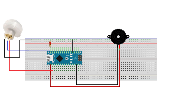
So let’s get started with connections, PIR sensor has three pins VCC, OUT, and Ground. Pin diagram of the PIR sensor is shown below. VCC is connected to 3.3V, OUT is connected to PORTB, and Ground is connected to the ground of Arduino microcontroller. The resistor is used as a pulldown resistor. Resistor one terminal is connected to the OUT pin of PIR and the other is terminal is connected to the ground. We used a buzzer for alerts whenever motion is detected.
Pin diagram of PIR Sensor

Schematic diagram
Code:
#define PIR 12
#define BUZZER 13

void setup(){
	Serial.begin(9600);
	pinMode(PIR, INPUT);
	pinMode(BUZZER, OUTPUT);
	Serial.println("Setup Completed");
	Serial.println("Motion Detection");
}

void loop(){
	if(digitalRead(PIR)){
		Serial.println("Motion Detected");
		digitalWrite(BUZZER, HIGH);
		delay(1000);
		digitalWrite(BUZZER, LOW);
	}
	else{
		Serial.println("No Motion");
	}
	delay(500);
}
Thanks for reading, for any assistance or doubts comment below.

