Table of Contents
About 7 segment display:
Seven segment displays are the output display device that provides a way to display information in the form of an image or text or decimal numbers. It consists of seven segments of light-emitting diodes (LED s) which are assembled like numerical 8. Since seven segment displays can not form an alphabet like X and Z, so it can not be used for the alphabet and it can be used only for displaying decimal numerical magnitudes. However, seven-segment displays can form alphabets A, B, C, D, E, and F, so they can also use for representing hexadecimal digits. The Working of Seven Segment Displays is explained below.

Checking 7-Segment Display with Multimeter
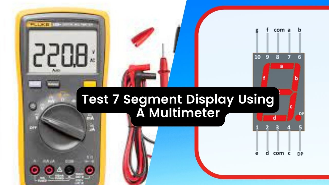
Testing individual segments of a 7 Segment display:
seven-segment displays will have a CC mark for the common cathode and a CA mark for the common anode.

The above figure shows both the variants of 7 segment displays i.e the common anode and common cathode.
Steps involved in testing:
- Hold the display in your hand and identify pin 1.
- Now take the multimeter (assuming a red lead for positive and a black lead for negative) and Keep the multimeter in diode mode shown in the below picture.

- Put your multimeter red lead on pin 3 or 8 as shown in the figure.
- Now put your meter’s black lead on any other pin such as 1,2,3,4 or 5 as shown in the figure.


- If any of the display’s segments glow then the display is a common anode.
- Connect your meter’s black lead to pin 3 or pin 8.
- Now put the red lead of the multimeter on another remaining pin as shown in the figure. If any of the segments glow then the display is a common cathode, as in a common cathode the negative pin is common and the rest are connected to a positive supply.

- Check all segments of both common cathode and anode to ensure the display is working properly.
- If no segment glows, this 7 segment is faulty.