Hi guys this article is to discuss the Lora module interfacing with the STM32F blue pill board. The driver is implemented to transmit and receive the data between two devices in Keil IDE using the HAL driver. This library mostly focuses on the Lora mode and uses SPI communication. In Lora mode, we can access 0x00 – 0x3F Lora registers. In this article, we cover only some registers for transmission and reception. For both transmission and reception, Lora module initialization should be the same then only the receiver module can able to demodulate the packet and read it successfully. Let’s see this tutorial in three steps Lora Initialization, Transmission, and Reception.
Table of Contents
1. Lora Initialization:
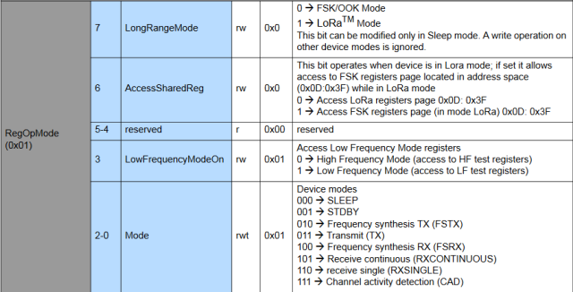
Here I am using the SX1278 LoRa module. For Initialization, we need to know about some registers of Lora. Lora works on two types of modulation techniques FSK/OOK and Lora. We use Lora modulation. For this, we need to set this in the Lora register RegOpMode(0x01). Let’s see the bits to be set in this register. These register values are the same for SX1276, SX1277, SX1278, and SX1279.

From the above image, we can observe that the 7th bit is ‘0’ means FSK/OOK mode, and ‘1’ means Lora mode. We have to set this bit ‘1’ as we use Lora mode.
Bits 3,4,5 and 6 are set to ‘0’. In the 3rd bit ‘0’ for High Frequency and ‘1’ for Low frequency.
From bits, 0-2 are for device mode setting. We mostly use four modes Sleep, Standby, Transmit, and Receive Single. In Sleep mode, we can access all the registers except FIFO. So, all the initialization and setting the registers in Sleep mode only. For the Transmitter device, we have to set in Transmit mode. For the Receiver device, we have to set in Receive Single mode.
Observe the below table for the value to be set in RegOpMode (0x01) register.
| Value | Mode |
|---|---|
| 0x80 | Sleep |
| 0x81 | Standby |
| 0x83 | Transmit |
| 0x86 | Receive Single |
Table 1: Device Modes
Next, we need to set the frequency for the module. This is very important for the device to device communication. For this we need to set values in three registers are RegFrMsb(0x06), RegFrMid(0x07) and RegFrLsb(0x08). The default frequency is 434MHZ, these values can be changed only by the device in Sleep or Standby mode. See the below table for values to be set for a particular frequency.
| Frequency (MHz) | RegFrMsb (0x06) | RegFrMid (0x07) | RegFrLsb (0x08) |
|---|---|---|---|
| 433 | 0x6C | 0x40 | 0x00 |
| 865 | 0xD8 | 0x40 | 0x00 |
| 866 | 0xD8 | 0x80 | 0x00 |
| 867 | 0xD8 | 0xC0 | 0x00 |
2. Transmission:
For transmission, we need to set the device in Standby mode. Then only we can access the FIFO register. Next, write the transmission data to the RegFifo(0x00) register. The maximum size of the FIFO is 256 bytes. So, have to choose the data in this length only. Next, we have to keep the device in Transmit mode (See Table 1). Now, wait for transmission done, TxDone interrupts flag is raised in the RegIrqFlags(0x12) register. Now clear the IRQ flags for the next transmission.
3. Reception:
Initially set the device in Receive Single-mode (See Table 1). Check the IRQ RxDone and ValidHeader whether these flags are raised or not in RegIrqFlags(0x12) register. If these flags are set means we received the packet with valid PayloadCrc. Then read the received length of data in RegRxNbBytes(0x13) register and data from RegFifo(0x00).
Let’s See the components required.
Components Required:
- STM32 blue pill boards – 2
- Lora SX1276/7/8/9 – 2
- ST-LINK – 2
- FTDI – 2
- Breadboard – 2
- Jumper wires
Schematic Diagram:
The schematic diagram is the same for the transmitter and receiver.

Connection for FTDI with Bluepill:
| FTDI | BluePill |
|---|---|
| RX | A9 |
| TX | A10 |
| VCC | 3.3V |
| GND | GND |
Connection of LoRa with BluePill:
| LoRa | BluePill |
|---|---|
| VCC | 3.3V |
| GND | GND |
| NSS | A4 |
| MISO | A6 |
| MOSI | A7 |
| SCK | A5 |
| RST | B0 |
You can download the schematic of Fritzing file.
Code:
Go to the MDK-ARM folder and find lora.uvprojx, open this file in Keil software. Open main.c file, in this file both transmitter and receiver code, is there. For Transmitter, comment the line #define RX and uncomment #define TX line. Build the code and Burn code to device1. For Receiver, comment the line #define TX and uncomment #define RX line. Build the code and Burn code to device2.
#include "main.h"
#include "lora.h"
#include <string.h>
#include <stdio.h>
#define TX // Uncomment for Transmission
//#define RX // Uncomment for Reception
Thanks for reading, for any assistance or doubts comment below.Thanks for reading, for any assistance or doubts comment below.
